Sketching during Schematic Design
So what exactly is schematic design? In short order, schematic design is the initial design phase in any project. The first step is called programming which is when the client and architect discuss the requirements of the project (how many rooms, the function of the phases, etc.), testing the fit between the owner’s needs, wants, and budget. This first phase is incredibly important but it is a fact-finding and data collection process. The first time I get to put pen (or pencil) to paper is during the schematic design process.
Let’s get a bit more specific on what schematic design actually means – the architect prepares a series of rough sketches which show the general arrangement of rooms and their placement on the site. I generally like to assemble all the information I have collected during the programming phase and start blocking out initial diagrams that describe the physical parameters of the project. Normally this is in the form of quick sketches The homeowner approves these sketches before proceeding to the next phase which is Design Development.
I think I’ll talk about the design development phase in a separate post because today is dedicated to the sketches behind the latest project we just started.
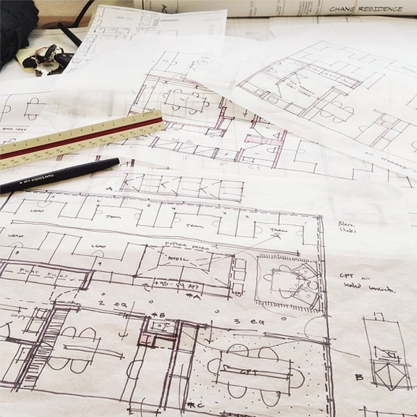
This is a pile of sketch paper from the time I was working through the layout of our new office. Sketch paper is typically where I do all of my schematic design work – not on the computer. I am constantly going through layers and layers of sketches to quickly work through ideas and if I was a betting man – which I’m not – I would say that this process is what has developed my sketching techniques.
I actually almost barfed when I typed in the word “technique” …
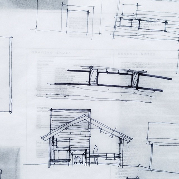
Despite the fact that schematic design is typically associated with the plans – determining room sizes and adjacency – I typically have some sort of idea of the elevations in mind as I am laying out these spaces and as a result, my schematic design sketches are typically dotted with potential details and elevation studies.
So to focus in on my process of schematic design, I thought I would focus in specifically on a single project. This one was a little different from most in that I had very little time to develop this plan. From the time of my initial meeting, I had less than a week to turn the initial programming information into a coherent plan for a house that is approximately 5,000 square feet. We are lucky to be really busy and most of the initial design work was done in my head (I was probably standing in the shower staring at the tile work).
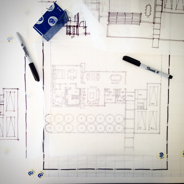
I thought I would show this picture even though it is out of sequence with the other sketches. Once I have my list of rooms, sizes and adjacency worked out, I tape a large piece of paper down that has a 1′ x 1′ grid (at 1/8″ scale) on my desk and use that as my dimensional control. You can see it in the image above but on this grid, every 8′ is a heavier line – it’s a good number to use because 8′ is a common building material increment. The grid keeps things relatively straight – which seems obvious but when you put layer upon layer of trace on top of one another, things start to move on you a bit. The grid helps you to reset every now and again.
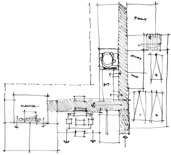
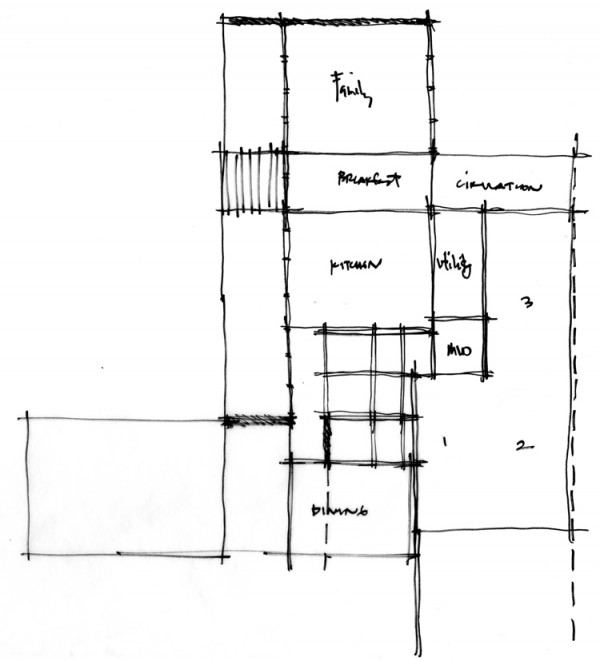
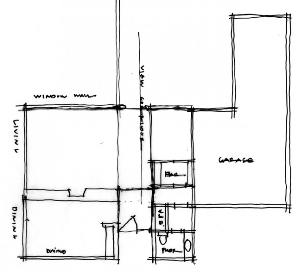
This was one of the very first bubble diagrams I created for this project. The clients want a fairly modern interior but don’t particularly like the idea of a really modern exterior … they want something a little in the middle. I’m okay with that, this is their house and they want to be considerate of the neighborhood – at least that’s what I’m telling myself. This is basically a 2 bar diagram, nothing too tricky here. The only issue I had was with the 3 car garage on the front of the house – something I really dislike. I am kind of stuck with it because this lot doesn’t have any alley access and the client said she didn’t want a driveway along the side all the way to a garage located in the back.
Fair enough.
Quick is really supposed to be the key ingredient in these studies. I’m not normally an advocate of quantity over quality but it seems (at least to how I works best) that if I work through a whole bunch of ideas really quickly, not focusing on the beauty of the sketch or its completeness that I get to the essence of the solution a bit faster.
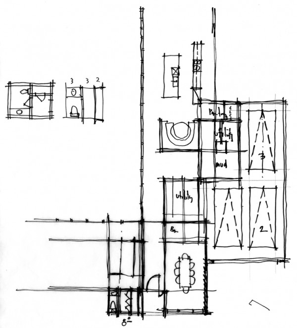
Typically I will work through individual room layouts that are modules – like toilet rooms, closets, pantry, etc. off to the side and I can just plug them in where I need them.
These are all in progression – again, I am working in layers.
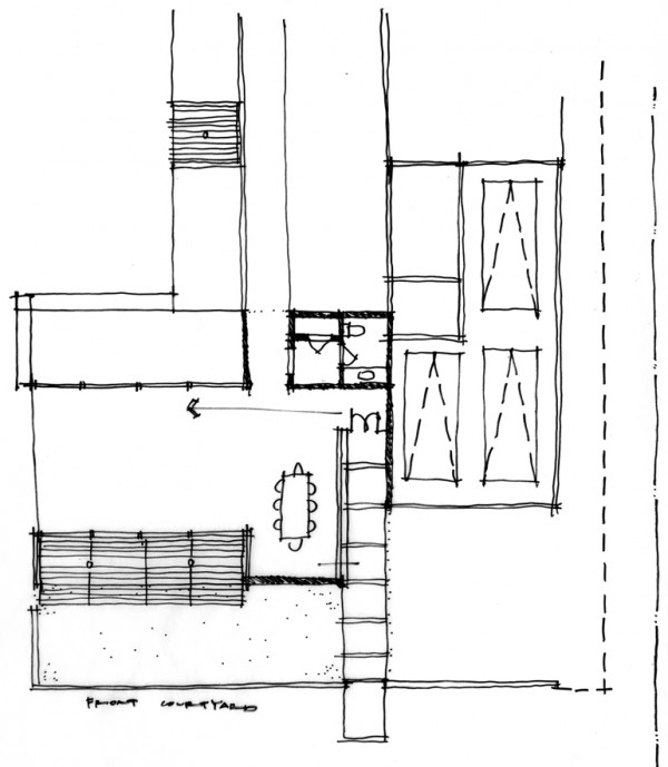
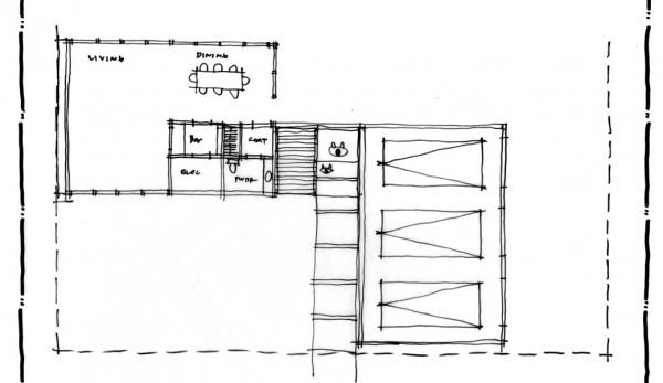
You all know that I hate toilet rooms right by the front door – hate them! This is not necessarily a proximity issue, it’s a visibility issue. I always try to group the toilet room that invariably wants to be located by the front door with a coat closet and vestibule – something that will act as a visual (and audible) buffer to that space.
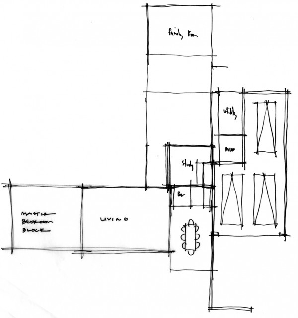
More toilet room studies and in this sketch, I was exploring changing the orientation of the Living and Dining rooms. We don’t get asked to do as many formal dining rooms as we used to – but they haven’t gone away altogether. I can’t help but think if you are going to have a 5,000 square foot house, a formal dining room should be part of the programming. These folks did want a dining room and from what few meetings we’ve had so far, it’s a space they use frequently.
.
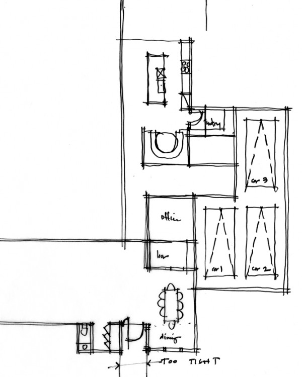
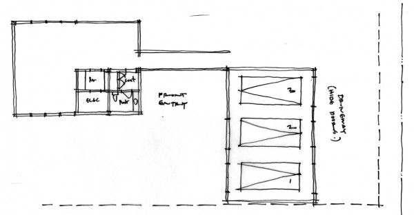
Oooo – I hijacked myself and decided to look at what would happen if I switched things around on the site and rotated the garage to the side.
It didn’t work … I mean, it could work but the cost up front from a land use standpoint would have been too high. Since I can’t place it in the rear of the lot, it has to be up front. Since our garages are typically 24′ deep (people drive big a** cars down here in the Lone Star State) and once you add an additional 24′ for backing in and out of the garage, the edge of the garage is now 48′ into the lot … and since the lot is only 100′ wide, this is too steep a price to pay.
Here is a better look at how far the house moves across the lot once you figure in the rotated garage.
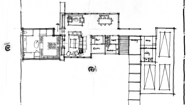
Back to the original garage layout. Things are still evolving and shifting locations.
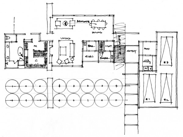
I know that landscaping isn’t generally a huge consideration during the schematic design phase but I am still thinking about it to a certain degree. All the circles shown in the sketch above represent trees in the front yard. There are some large windows that look into and through the house and I am simply inferring that I think we need some sort of landscape barrier between the house and the street.
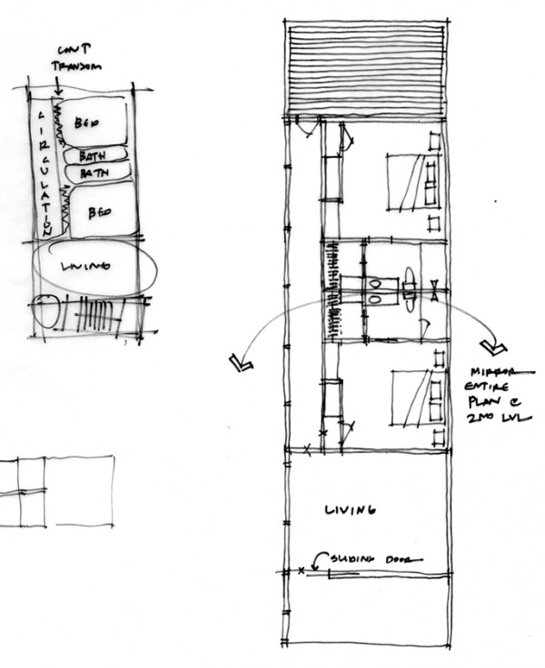
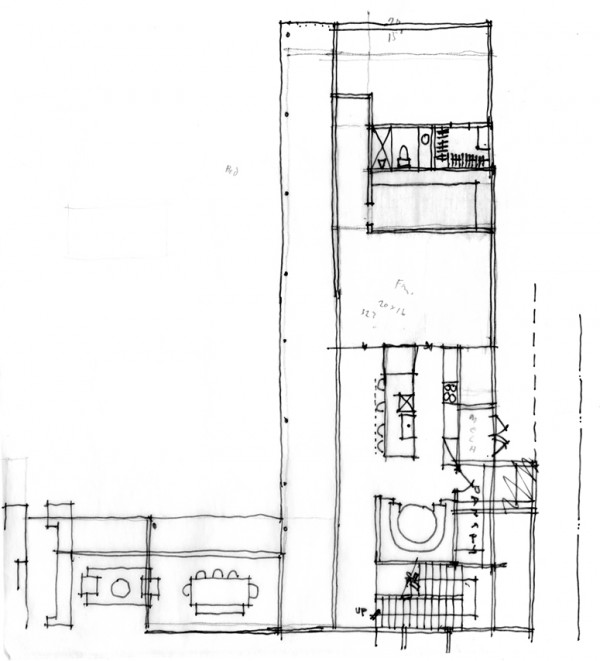
The second floor programming was very straight-forward once I had the location determined for the vertical circulation (architect way of saying “stairs”) laying out the upstairs living space and the children’s bedrooms was easy. So easy in fact, that I drew the entire thing mirrored from how I had wanted it.
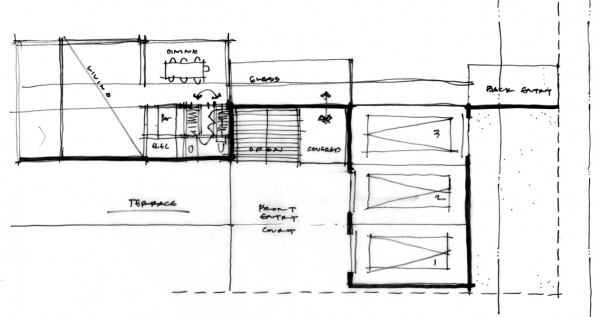
So I thought it might be interesting to see what all these sketches added up to as a semi-finished product. Everything I have shown you today was done in a single day. Granted, it was a long day but that’s my fault for filling up my calendar with too many activities. I literally finished these drawings, sent someone from the office to go get them copied (they waited for the copies) they were brought back to me where I added some hand-written labels, some color for the trees and walls, and left for my meeting.

Hopefully it is obvious that the image above is the ground floor plan …

… and this is the second floor plan.
The thing that I really love about this phase of the project is that it is so exciting to present these plans to the clients. I typically expect there to be some push back on something I’ve shown, or some assumption that I’ve made as the programming relates spatially to the form of the house .. and that is how it should be. This is not a house for me so I am invested in making sure that the client gets what they want. I had my second meeting with these clients last night – after they had some time to think about what is shown here – and there are some modifications that I will be working on today. Not a lot, and some I have already made in anticipation of receiving any formal instructions. These are pretty savvy clients and they have designed and had built 2 houses prior to starting this project. At the initial presentation, their comments were succinct and clear and I was able to make modifications just by paying attention to listening as the husband and wife discussed what they wanted to one another while I was sitting there.
I’ve got more sketching to do but I think it’s safe to say that we will be leaving the schematic design phase after about 2 weeks time and will begin “Design Development”. I’ll try to plan ahead of time and prepare a post on that process as well.
Cheers – and happy sketching.
Shared by - Mriganka Banikya
Copied from - www.lifeofanarchitect.com
No comments:
Post a Comment